Level 1: Drivetrain and Power MANAGEMENT
Drivetrain Construction and Managing:
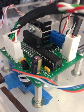
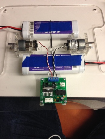
As soon as the early laser cutting process finished, we began to hit the ground running as soon as possible with mounting. As discussed, we didn’t initially cut any mounting holes, reasoning that we could drill in acrylic as we went. Ideally, I would have liked to fully prototype and cut all of the holes with the laser, however, given our limited time, we wanted to get things built as soon as possible. Our first goal was to start building the drivetrain and wheel system. We began by soldering together our L298 chip (shown at left) and constructing all of the wires and Molex connectors for this. From here, the mounting process began. We mounted the motors using the designed motor mounts in CAD. From there, we soldered leads to the motors and hooked them up to the screw terminals of the L298. The next major milestone came with beginning to mount the L298, which involved drilling the first holes in the acrylic. It took a little practice, but we found with a high-powered drill and a sharp bit, we were able to drill very direct and refined holes with a high degree of accuracy. Below right you can see how the base of the robot looked after we mounted the motor and the batteries. The batteries were simply mounted using pieces of wire through drilled holes. We then mounted the wheel bearings on the driveshaft of the motor.
As soon as the early laser cutting process finished, we began to hit the ground running as soon as possible with mounting. As discussed, we didn’t initially cut any mounting holes, reasoning that we could drill in acrylic as we went. Ideally, I would have liked to fully prototype and cut all of the holes with the laser, however, given our limited time, we wanted to get things built as soon as possible. Our first goal was to start building the drivetrain and wheel system. We began by soldering together our L298 chip (shown at left) and constructing all of the wires and Molex connectors for this. From here, the mounting process began. We mounted the motors using the designed motor mounts in CAD. From there, we soldered leads to the motors and hooked them up to the screw terminals of the L298. The next major milestone came with beginning to mount the L298, which involved drilling the first holes in the acrylic. It took a little practice, but we found with a high-powered drill and a sharp bit, we were able to drill very direct and refined holes with a high degree of accuracy. Below right you can see how the base of the robot looked after we mounted the motor and the batteries. The batteries were simply mounted using pieces of wire through drilled holes. We then mounted the wheel bearings on the driveshaft of the motor.
Designing the Power System
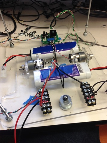
The next major step was designing a power management system. We had access to two 7.4V batteries, and wanted the ability to provide as much power as possible to the drivetrain. On the other hand, we need to be able to provide a voltage closer to 5V in order to power the Arduino. We therefore needed to be able to provide these two raw outputs at the battery themselves. If we feed 7.4 into the Arduino’s Vin, it will self regulate down to 5V and 3.3V for us. Therefore, the circuit at the batteries will look like so. Implementing this on the robot was relatively straightforward. We mounted two sets of screw terminals on the body of the robot and wired them up to 7.4V and 14.8V. This can be seen on the image below. This manner of managing power was very effective, as it gave us a high level of flexibility and capability, while simultaneously allowing us to source as much current and voltage that we needed.
The next major step was designing a power management system. We had access to two 7.4V batteries, and wanted the ability to provide as much power as possible to the drivetrain. On the other hand, we need to be able to provide a voltage closer to 5V in order to power the Arduino. We therefore needed to be able to provide these two raw outputs at the battery themselves. If we feed 7.4 into the Arduino’s Vin, it will self regulate down to 5V and 3.3V for us. Therefore, the circuit at the batteries will look like so. Implementing this on the robot was relatively straightforward. We mounted two sets of screw terminals on the body of the robot and wired them up to 7.4V and 14.8V. This can be seen on the image below. This manner of managing power was very effective, as it gave us a high level of flexibility and capability, while simultaneously allowing us to source as much current and voltage that we needed.
Finalizing the Base Layer
At this point, we need to add three more very basic things to the bottom layer. First and foremost, we needed wheels. We wanted to get the wheels on as soon as possible so that we could start testing our maneuverability. However, to do this we needed to build a secondary set of wheel mountings to support the weight of the robot. These were CADed together and cut on the laser. After adding these wheel mounts, we were able to perfectly align the wheels and start experimenting with motion. This was another major milestone, as it allowed us to start driving our little half-robot around. To increase stability, we needed to mount two caster wheels along the major axis of the robot perpendicular to our driveshafts. This was very straightforward. It did take a little bit of experimenting with washers to get the right height for the caster wheels. At this point, we had a fully functioning drivetrain. The last thing we needed to mount on the base layer was the tape sensors used to detect tape. Our initial ideas for game philosophy required the use of two tape sensors, one at the axis of rotation and one farther along the forward axis. We mounted these in the center hole cut for wires and directly underneath the L298.
At this point, we need to add three more very basic things to the bottom layer. First and foremost, we needed wheels. We wanted to get the wheels on as soon as possible so that we could start testing our maneuverability. However, to do this we needed to build a secondary set of wheel mountings to support the weight of the robot. These were CADed together and cut on the laser. After adding these wheel mounts, we were able to perfectly align the wheels and start experimenting with motion. This was another major milestone, as it allowed us to start driving our little half-robot around. To increase stability, we needed to mount two caster wheels along the major axis of the robot perpendicular to our driveshafts. This was very straightforward. It did take a little bit of experimenting with washers to get the right height for the caster wheels. At this point, we had a fully functioning drivetrain. The last thing we needed to mount on the base layer was the tape sensors used to detect tape. Our initial ideas for game philosophy required the use of two tape sensors, one at the axis of rotation and one farther along the forward axis. We mounted these in the center hole cut for wires and directly underneath the L298.
The Bumper System
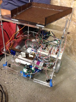
The final step to complete the base layer of the robot was to mount the front bumpers. We opted to only use two bumpers on the front of the robot. They were very simple in concept. They just involved mounted acrylic arms which tapped on a roller button switch when pressed. You can see this on the front of the finished robot at right. They were mounted using a couple loose washers and M3 screws. This gave them the full ability to move. The two switches were very carefully mounted such that they would be fully depressed when pressed so they would be flush to the front of the robot. The only remaining challenge was to figure out a way to ensure that the bumper parts don't swing outward. To fix this, we made a simple tie to the supporting rods out of tape. These bumpers worked perfectly.
The final step to complete the base layer of the robot was to mount the front bumpers. We opted to only use two bumpers on the front of the robot. They were very simple in concept. They just involved mounted acrylic arms which tapped on a roller button switch when pressed. You can see this on the front of the finished robot at right. They were mounted using a couple loose washers and M3 screws. This gave them the full ability to move. The two switches were very carefully mounted such that they would be fully depressed when pressed so they would be flush to the front of the robot. The only remaining challenge was to figure out a way to ensure that the bumper parts don't swing outward. To fix this, we made a simple tie to the supporting rods out of tape. These bumpers worked perfectly.
