CAD
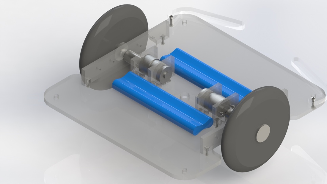
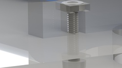
CAD designing was an integral first step in the build process, since it enabled us to visually organize the important sub-assemblies of the robot. By knowing the dimensions of the various parts (such as motors, batteries, and wheels), the drivetrain mechanisms could be designed, which provided an accurate representation of the space available in design constraints. It also made designing fastening mechanisms easier, since a standard toolkit of parts could be used to check hold spacing, or other retention mechanisms.
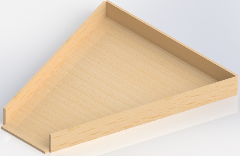
The second benefit of using CAD to design the major components of the robot was that it was easy to then export drawings of the parts to laser-cutter-compatible files. By using primarily acrylic, laser cutting enabled faster prototyping than either direct machining or CNC machining would allow. Unfortunately, this also meant we were limited to 2D projections (or extrusions) instead of fully 3D parts.
It turned out that modeling the entire robot wasn't necessary, since some of the components could have been placed anywhere space was available, but the important components of the drivetrain, and any laser-cut parts were modeled.
It turned out that modeling the entire robot wasn't necessary, since some of the components could have been placed anywhere space was available, but the important components of the drivetrain, and any laser-cut parts were modeled.
Ultimately, the CAD model allowed us to create a base design for our robot, and check that the design had enough tolerance to ensure that different components wouldn't interfere.
Below are the SolidWork files. The contain all of the CAD work done for the robot.
Below are the SolidWork files. The contain all of the CAD work done for the robot.
| solidworks.zip |
